What is the difference between a capacitor and an inductor?
In this article, we will learn about two basic electronic components: capacitors (very common in circuits) and inductors (less common but often cause a lot of trouble). This article will not go into practical applications but focus on analyzing the physical aspects of these two components, to help you understand the operating principles as well as how to use them in the circuit analysis process.
Contents
Capacitor
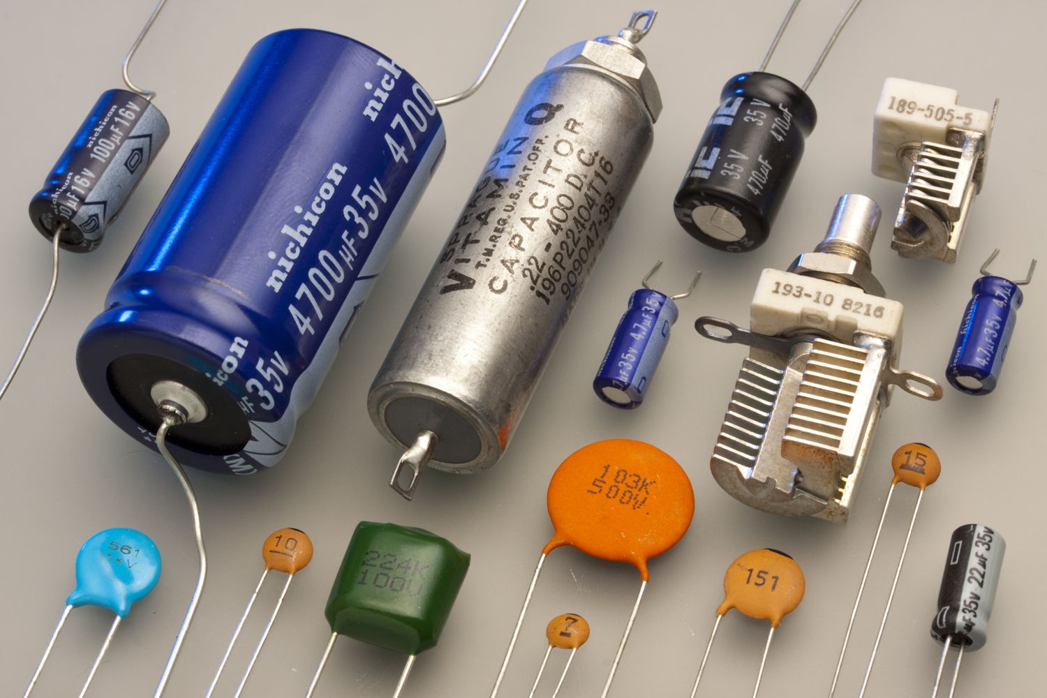
Capacitors are a familiar component in most electronic circuits, and in some cases, people encounter capacitors more than resistors. This type of component has two legs and is represented by a special symbol in the circuit diagram. The legs of the capacitor can be non-polarized or polarized (ie, there is a distinction between positive and negative poles). For polarized capacitors, it is mandatory to supply the correct voltage direction for the capacitor to operate stably, specifically the positive leg must be connected to a higher voltage level than the negative leg.
A capacitor is a component that can store electric charge. It consists of two conducting plates separated by an insulating layer called a dielectric. When these two plates carry opposite charges, an electric field is formed and creates a potential difference between the two ends of the capacitor. The relationship between voltage and the amount of charge in a capacitor is described by the formula:
In the above expression, u is the voltage across the capacitor in Volts, q is the amount of charge the capacitor stores (in Coulombs) and C is the capacitance, which represents the capacitor's ability to store charge, measured in Farads. In practice, common capacitors usually have capacitance values ranging from microfarads (uF) to nanofarads (nF). The larger the capacitance C, the more charge the capacitor can store for the same voltage level. The capacitor can be visualized as a water tank: u represents the height of the water level, q is the amount of water contained inside and C is the bottom area of the tank.
When there is a change in voltage between the two electrodes, for example a decrease in voltage, the amount of charge will change. This leads to the formation of a current, which slows down the change in voltage. Since current is the movement of charge, when a capacitor loses charge, a current will form and flow out of the capacitor in response to the change. Therefore, people use capacitors to help stabilize the voltage between the two ends of the capacitor.
Another way of understanding this is that a capacitor stores energy in the form of electric potential energy. This energy is proportional to the square of the voltage across the plates. When the capacitor voltage drops, the electric field energy is released and creates a current, which counteracts that change. Conversely, when the voltage increases, the capacitor absorbs this energy and the current slowly flows into the capacitor. If you short-circuit the capacitor while it is charging, all the energy will be released in the form of a very strong electric current, which can even cause sparks. If you want to keep the energy in the capacitor, leave the two ends open, because no current can flow through.
With DC, since the voltage does not change, the capacitor does not generate current. However, if you use AC, the capacitor must continuously generate current to respond to the continuous fluctuations in voltage. As the frequency of the fluctuations increases, more current must be generated, resulting in a capacitor with low resistance to AC. So in AC, the capacitor acts as a conductive path. A practical application of this principle is to eliminate DC components in audio circuits such as speakers or microphones.
In short, a capacitor can be understood as a component that helps slow down the change in voltage between two ends by creating a corresponding current. It stores a type of energy called electric potential energy, which is proportional to the voltage stored on the capacitor, and has the ability to supply or absorb energy depending on the requirements of the circuit. The capacitor does not react significantly to direct current, but works strongly when exposed to alternating current.
Inductor
Inductors are not as common as capacitors in common electronic circuits, but they are a component that causes a lot of "trouble" when designing. In terms of shape, they have two pins, are non-polarized, and can be inserted in either direction without affecting the function.
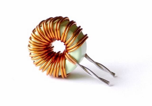
An inductor is a device that stores magnetic fields. Although the concept may not be as familiar as a capacitor, magnetic fields are actually a form of energy, and can be “stored” just like electric charges. An inductor is a wire wound into multiple loops, sometimes around an iron core for added efficiency. When an electric current flows through the wire, the coil generates a magnetic field. This magnetic field in turn generates an induced voltage that counteracts the change in current in the coil. The formula that describes this phenomenon is:
In which, u is the voltage across the inductor, i is the current through the coil, and L is the inductance – indicating the ability of the inductor to store a magnetic field, measured in Henry units. The larger L, the more “resistant” the inductor, the more strongly it resists rapid changes in current.
This phenomenon can be understood simply as follows: if the current through the inductor increases or decreases suddenly, the magnetic field in the coil must also change accordingly. But the magnetic field cannot change immediately, so it generates an opposite voltage to “slow down” that change. Therefore, the inductor slows down the change in current through it, similar to how a capacitor slows down the change in voltage.
Another way of looking at it is that the inductor stores energy in the form of magnetic potential energy, proportional to the square of the current. When the current through the coil decreases, the magnetic energy is released, generating a voltage to “compensate” for the lost current. Conversely, when the current increases, the coil absorbs energy from the circuit, but does not do so immediately, but gradually through the induced voltage. It is this slowness that makes the inductor capable of causing many undesirable phenomena if not handled properly.
An example is when an inductor is conducting current and suddenly has an open circuit, the current is cut off immediately, the inductor has no way to discharge the magnetic field. As a result, it generates a very large voltage to maintain the current, which can burn components, damage transistors, ICs, or create sparks at the switch. That is why people often add discharge diodes to motor control circuits or IC output ports to protect the circuit.
When used in a DC circuit, the inductor does not provide much resistance because the current does not change, so there is no significant induced voltage. But in an AC circuit, the current is constantly changing, causing the inductor to continuously create an induced voltage to resist, thereby limiting the current. The higher the frequency, the stronger the variation, the more the inductor blocks the current. Therefore, the inductor is a very useful component for filtering noise in power circuits or eliminating high frequency signals.